+1 (226) 337-9660

 English
Search

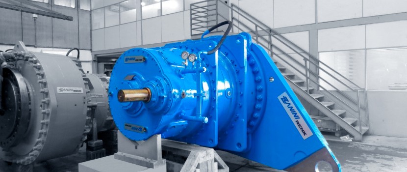
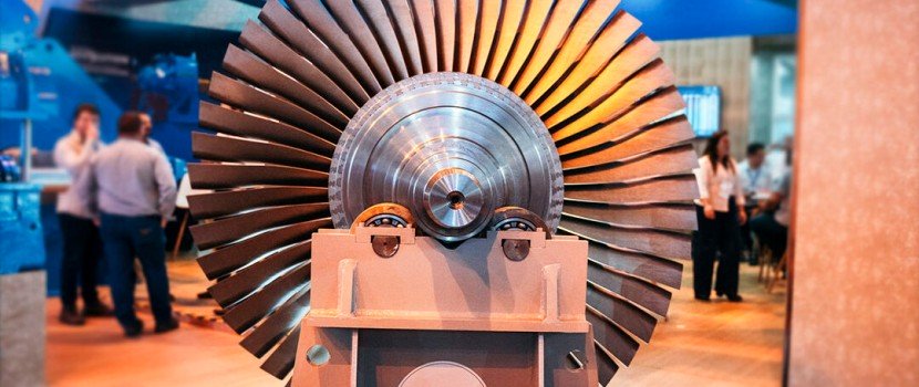
Choosing the right industrial gearbox is one of the most critical decisions in an industrial project. The gearbox is the mechanical link that ensures energy efficiency, operational reliability, and long equipment lifespan across the entire power transmission system.
Improper industrial gearbox sizing can lead to overloads, excessive heat, noise, vibration, and premature failures. In real industrial environments, these issues quickly translate into unplanned downtime, higher maintenance costs, and reduced plant productivity.
Understanding how to correctly specify and size an industrial gear reducer is essential for achieving safe, efficient, and durable operation.
Before performing any gearbox sizing calculations, it is essential to fully understand the application. Every industrial process imposes different requirements related to torque, load behavior, duty cycle, and operating environment.
For example, a continuous conveyor system behaves very differently from an intermittent mixer or a crusher exposed to frequent load variations. These differences directly affect gear reducer selection and service life.
Answering these questions allows the correct definition of the service factor, which adjusts gearbox sizing to account for real operating severity. The more demanding the application, the higher the service factor must be.
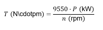
Torque is the fundamental parameter in industrial gearbox sizing. It represents the mechanical effort required to move the load and is calculated based on motor power and desired output speed.
For power expressed in kilowatts (kW) and rotational speed in revolutions per minute (RPM), the required output torque is calculated as:
Inverse:
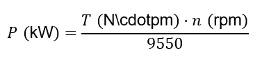
This calculated value represents the required torque that the industrial speed reducer must handle continuously without compromising gears, shafts, or bearings.
In practice, correct torque sizing provides a safety margin to accommodate load fluctuations, transient peaks, and real-world operating conditions.
The reduction ratio, also referred to as gear ratio, defines the relationship between the motor input speed and the required output speed.
For example, a motor running at 1,500 RPM connected to an industrial gearbox with a 30:1 reduction ratio will deliver an output speed of approximately 50 RPM.
Selecting the correct reduction ratio requires balancing:
The gearbox type (helical, bevel, planetary, or combined configurations) and the number of stages directly influence efficiency, noise levels, and footprint.
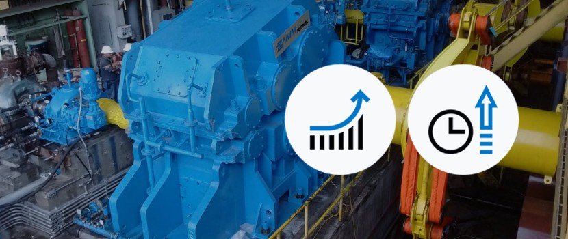
Multi-stage industrial gear reducers are often preferred for large reductions, as they deliver high efficiency, smooth operation, and lower noise, ideal for continuous-duty applications.
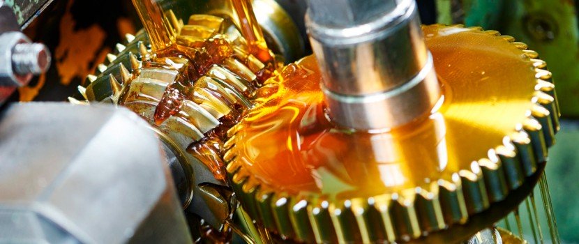
Not every industrial gearbox that meets torque requirements is suitable for continuous operation. During power transmission, part of the mechanical energy is converted into heat. If this heat is not properly dissipated, oil temperature rises, accelerating wear and reducing component life.
This is why verifying the thermal capacity of the gearbox is critical. Thermal capacity defines the maximum power the gearbox can dissipate without overheating.
When heat generation exceeds this limit, additional solutions such as:
may be required to ensure stable thermal conditions and reliable long-term operation.
The mounting configuration of the industrial gearbox, horizontal, vertical, or shaft-mounted, directly affects oil distribution, thermal behavior, and bearing loads.
Equally important is the connection method:
Proper alignment between the motor, gearbox, and driven equipment is essential. Misalignment increases vibration, bearing loads, and mechanical stress, significantly reducing gearbox lifespan.
For this reason, installation must strictly follow the manufacturer’s alignment tolerances and mounting recommendations.
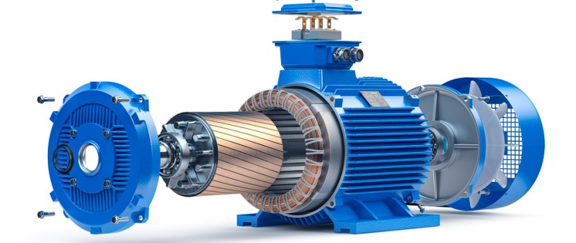
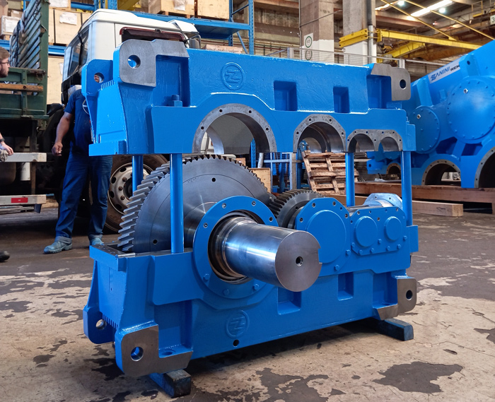
The durability of an industrial speed reducer depends heavily on the quality of its materials and internal components.
At RSG Zanini Renk, gears are manufactured from case-hardened alloy steels, such as 18CrNiMo7-6, and precision ground to achieve high fatigue strength, dimensional stability, and optimized load distribution.
Bearings are selected for heavy-duty operation and long service life, while sealing and lubrication systems are designed to perform reliably in harsh industrial environments.
This combination results in:
Before finalizing the gearbox specification, several additional factors must be evaluated:
These checks ensure that the industrial gearbox is not only theoretically correct but also robust under real operating conditions. This is what distinguishes basic gearbox selection from true engineering-driven gearbox specification.
Proper industrial gearbox sizing is not just about calculations it is about understanding the application and translating operating variables into reliable mechanical performance.
When this process is conducted with technical rigor, the result is a gearbox operating at the optimal balance between efficiency, safety, and durability.
At RSG Zanini Renk, gearbox sizing and selection are carried out by specialized engineering teams that combine practical experience, digital simulation, and metrological analysis to deliver engineered-to-order industrial gear reducers for demanding applications.
Contact the specialists at RSG Zanini Renk and discover how proper industrial gearbox sizing can significantly improve the performance, reliability, and lifespan of your power transmission system.